4.2. Set-up procedure
4.2.1. Preliminary procedure
Important
Before installation, check the integrity of the equipment by following the Delivery control procedure.
Note
By replacing a multimode LC duplex optical jumper with two jumpers of the same type
By using the switch's mirroring ports, if so equipped
- Apply the good practices for inserting a Tap on a network.If necessary, contact the Gatewatcher support or your usual Gatewatcher contact.
Procedure for installing the GTaps in a rack :
Insert the GTaps into the rack until you hear a click indicating that they are secured in the internal rails.
If the GTaps are difficult to insert into the rack, check that the internal rails are at the bottom of the rack and that the GTaps are aligned with the internal rails, with the front panel text vertically aligned.
Note
A 19-inch rack can hold up to six GTap_O_MM.
If necessary, mount the rack in a bay and secure it.
Note
The height of the GTap rack is 1U.
Important
4.2.2. Procedure
Connection to the network to be monitored:
Connect the multimode LC duplex optical jumper of the network to be monitored to the
`NET A`port.Connect the multimode LC duplex optical jumper of the network to be monitored to the
`NET B`port.
Note
For each jumper, remove the covers protecting the fibers and connect the jumper.
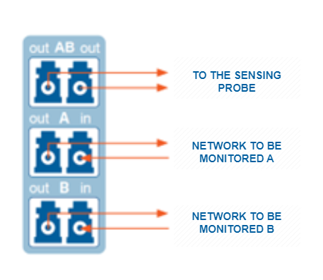
Connection to the sensing probe:
Connect the
`TAP AB`port to the sensing probe using a split duplex jumper.Connect the jumpers as shown in the diagram below: