1.5. Interconnection of subsets
1.5.1. Reminder of the GCap connections
Depending on the timing and configuration chosen, and looking from behind from left to right, the GCap is connected via:
a network socket for connecting a KVM / iDRAC
a USB and VGA connector for a keyboard and monitor
capture and monitoring interfaces
mon0,mon1,mon2,monxfor connecting TAPsthe network interfaces
gcp0andgcp1
Depending on the chosen configuration - single or dual interface - it is possible to use these network interfaces for connecting to the GCenter.the connectors for the GCap power supplies
For more information on the connection description, please refer to the Description of GCap inputs/outputs.
Note
Remember to connect the LUKS decryption key to the USB port.
1.5.2. Capture and monitoring interfaces monx between TAP and GCap: aggregation possibility
The GCap probe must read in a single flow; the network flow that has been captured in both directions:
an uplink,
a downlink.
To do this, the flows from each of the links must be aggregated into a single flow. There are 2 solutions for this:
either the flows were captured and aggregated by an aggregator TAP
or the flows were captured but not aggregated by a non-aggregating TAP
1.5.2.1. Capture mode with an aggregator TAP
In this situation, the GCap retrieves the flow aggregated by the TAP on a single monx capture interface.
This solution is preferable because it requires the least amount of GCap resources for the same flow.
1.5.2.2. Capture mode with a non-aggregating TAP: GCap mode with aggregation ("cluster")
This functionality is necessary if the Test Access Port (TAP) present in the architecture does not provide the interface aggregation functionality.
A qualified TAP is at least a passive or non-intelligent (simple) TAP. This means that it does not require its own power supply and does not actively interact with other components. Most passive TAPs do not have an embedded configuration.
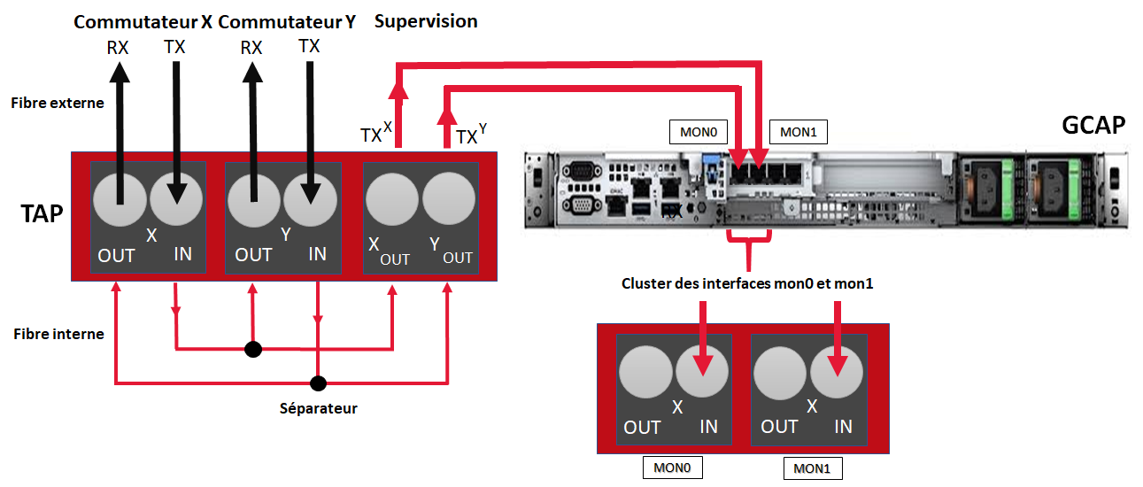
Connection between TAP and GCap
Unlike network interfaces where traffic is both TX (emission) and RX (reception), capture interfaces are unidirectional. Therefore, they can only receive flow, hence the following connection.
Each physical fibre link handles two links:
an uplink, i.e. a TX link
a downlink, i.e. an RX link
The TAP (without aggregation) is connected to the network via 2 physical links called commutateur X and commutateur Y.
The commutateur X link connects the switch and the X input TAP and enables duplicating half the network flow.
The TX link is:
connected to IN of the X connector
the flow of the TX link is copied to OUT of the Y connector: this is connected to the RX link of the
commutateur Yphysical linkthe flow from the TX link is also copied to the Xout link which is sent to the input port of the GCap (IN link of the
mon1port)
The commutateur Y link connects the switch and the Y input TAP and enables duplicating the other half the network flow.
The TX link is:
connected to IN of the Y connector
the flow of the TX link is copied to OUT of the X connector: this is connected to the RX link of the
commutateur Xphysical linkthe flow from the TX link is also copied to the Yout link which is sent to the input port of the GCap (IN link of the
mon0port)
Aggregation of interfaces (or clustering)
By defining an aggregation of two interfaces, the GCap aggregates these two flows into a single one, thus enabling a correct flow interpretation.
If the GCap has this functionality, this is not neutral in terms of resources allocated to this processing, hence the configuration with an aggregator TAP should be preferred.
1.5.2.3. Using and configuring interface aggregation
To implement interface aggregation, refer to the Procedure for managing capture interface aggregation.
1.5.3. Transferring rules between GCenter and GCap: single-tenant vs. multi-tenant
For more information, please refer to the paragraph Capture and monitoring interfaces: single-tenant vs multi-tenant.