1.3. GCap
GCap is a probe-type component.
It enables:
capturing and analysing network traffic from TAPs
generating events, alerts, and metadata
rebuilding the files contained in the flow
communicating with the GCenter
1.3.1. Different server models
For more information, please refer to the Characteristics section.
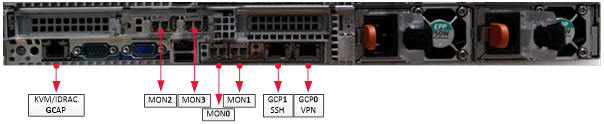
1.3.2. Description of the GCap inputs / outputs
The GCap detection probe features:
a USB and VGA connector to directly access a keyboard and a monitor. This connection mode is deprecated in favour of KVM/IDRAC/XCC and should only be used as a last resort
a USB connector accommodates the USB key enabling disk decryption (standard Linux Unified Key Setup)
one RJ-45 connector to access the server management and configuration interface (KVM/IDRAC/XCC)
two RJ-45 connectors
gcp0andgcp1RJ-45 and/or fibre connectors for monitoring
mon0Two power supplies
1.3.2.1. Use of USB and VGA connectors
Connecting a keyboard and monitor enables direct access to the server's console interface.
Important
This mode is deprecated. It should only be used during initial installation and for advanced diagnosis.
1.3.2.2. Access to the server's management and configuration interface
Access to this management interface is via HTTPS:
on a Dell server, this connector is called iDRAC. It is noted on the KVM/IDRAC GCap diagram
on a Lenovo server, this connector is called TSM. This connector can be identified by a wrench symbol on the bottom of it.
1.3.2.3. Interface network gcp0 and gcp1
These interfaces perform the following functions:
function 1: secure communication between the probe and GCenter through an IPSEC tunnel in order to:
escalate information such as files, alerts, metadata, and so on, derived from analysing the monitored flows
report information on the health of the probe to GCenter
control the probe - analysis rules, signatures, and so on.
function 2: remote administration through the SSH protocol with access:
to the probe's command line interface (CLI)
To the graphical setup/configuration menu (deprecated)
In single-interface configuration, these functions are supported by the gcp0 interface only
In dual-interface configuration:
function 1 is handled by interface
gcp0function 2 is handled by interface
gcp1.
1.3.2.3.1. Configuration of the gcp0 and gcp1 network interfaces
For more information on these interfaces and their configuration, refer to the section Network interfaces gcp0 and gcp1.
1.3.2.4. capture and monitoring interfaces
These interfaces receive:
flows from the TAPs on the indicated interfaces (
mon0andmonx),the flow from previously recorded files (pcap files) on a dedicated
monvirtinterface.
Note
The number of capture interfaces varies depending on the specifications of each model.
1.3.2.4.1. Activating the capture and monitoring monx interfaces
For more information, please refer to the paragraph Capture and monitoring interfaces: activation.
1.3.2.4.2. Aggregating the capture and monitoring monx interfaces
For more information, see the paragraph Capture and monitoring interfaces between TAP and GCap: aggregation capability.
1.3.3. Electrical connection
The probe has two power supplies, each of which has the necessary power to operate the equipment.
It is strongly recommended that each power supply should be connected to a separate power supply.
1.3.4. USB connector and LUKS key
During installation, the contents of the disks (excluding /boot) are encrypted using the LUKS standard.
During this process, a unique encryption key is created and placed on the USB stick connected to the probe.
It is strongly recommended to make a copy of this key because, in the event of failure, the data on the disks will no longer be accessible.
Once the system is up and running, the USB stick should be removed and placed in a secure place (e.g. in a safe).