4.2. Set-up procedure
4.2.1. Preliminary procedure
Important
Before installation, check the integrity of the equipment by following the Delivery control procedure.
Note
By replacing an existing network cable with two tap-off cables to the Tap
By using the switch's mirroring ports, if so equipped
- Apply the good practices for inserting a Tap on a network.If necessary, contact the Gatewatcher support or your usual Gatewatcher contact.
Do not turn on the GTap.
If necessary, mount and secure the GTap in a rack (19 inches).
To install a rack, screw the GTap into a rack frame to obtain the following result:
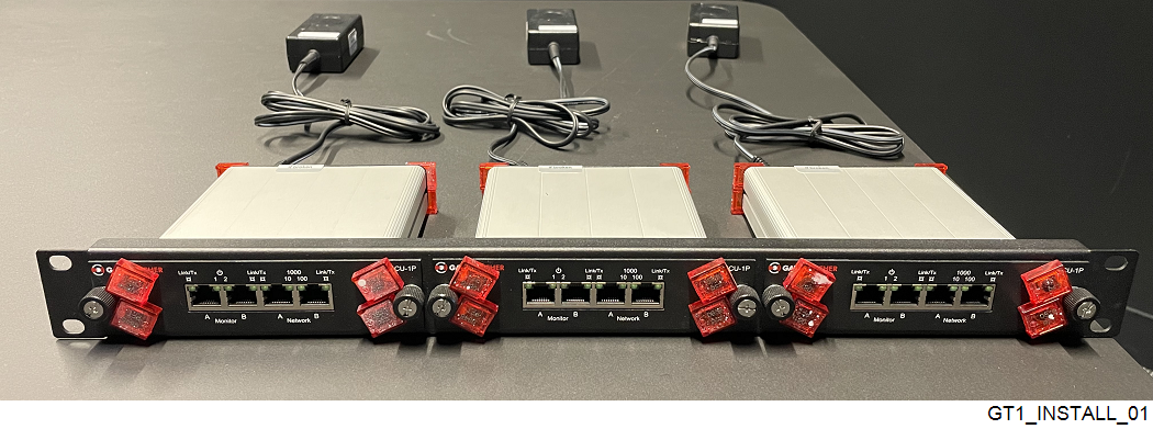
Three GTap rack
Note
The height of the three GTap rack is 1U.
4.2.2. Procedure
Connecting the GTap power cables:
Note
Recommendation: connect the GTap power supplies to two different feeders, themselves connected to separate power lines with different circuit breakers.
Connect the first power supply :
On one side to the <POWER 1> connector on the GTap
On the other side to the first feeder
Important
Use only properly grounded power cords and feeders.The feeders must remain easily accessible after the installation.Connect the second power supply if present:
On one side to the <POWER 2> connector on the GTap
On the other side to the second feeder
Checking the GTap power supply:
- Check that the <POWER 1> and <POWER 2> LEDs are lit.If this is not the case, check that the cables are correctly plugged into the sockets and that, if the rack is used, the rack's feeders are supplied with power.
Note
The <POWER 2> LED is lit only if a second power supply is connected to the GTap.
Connection to the network to be monitored:
Connect the cables of the network to be monitored to the
`Network A`and`Network B`connectors.- Use category 5e or higher RJ45 UTP cables.In the case of 10/100 MB network equipment that does not support auto-crossover:
Use two straight cables if network devices are of different types (one DTE and one DCE)
Use a straight cable and a crossover cable if the two network devices are of the same type (both DTE or both DCE).
- Checking the network flow to be monitored with the LEDs:
After negotiation on active and connected network ports, the LEDs light up steadily to indicate network speed:
LED 10 (1) is lit steady for a 10 Mb/s connection
LED 100 (2) is lit steady for a 100 Mb/s connection
Both LEDs are lit steady for a 1 Gb/s connection
The flashing means that a signal is detected and only one network cable is connected (LED Link/Activity).
- Check that the
`Network A`and`Network B`LEDs of the Tap are permanently lit.In the case of a bay installation, if a Tap unit's LEDs are flashing, check its cables and connections. - Check the activity of the network to be monitored.To do this, check that the LEDs on the Tap unit's
`Network A`and`Network B`are flashing rapidly.
Connection to the sensing probe:
Connect the Tap's
`Monitor A`and`Monitor B`ports to the sensing probe, using straight or crossover RJ45 UTP cables of category 5e or higher.Note
The network traffic received on the port`Network A`is duplicated on the port`Monitor A`and network traffic received on the port`Network B`is duplicated on the port`Monitor B`.The maximum distance between connected devices is 100 meters.
Checking the flow of the network to be monitored with the LEDs:
Note
The monitored`Monitor`ports operate at the same speed as the`Network`input ports.