1.6. Interconnection between devices
1.6.1. Viewing communication flows
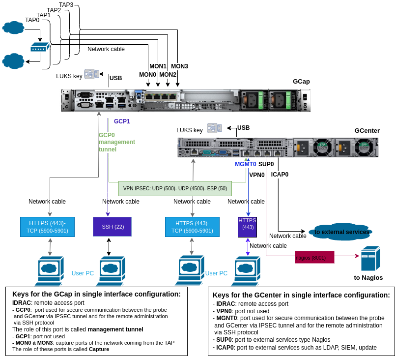
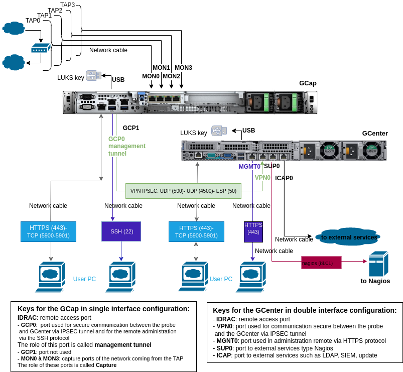
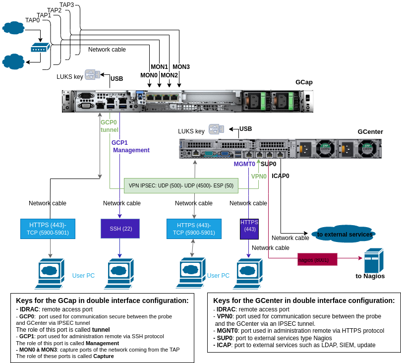
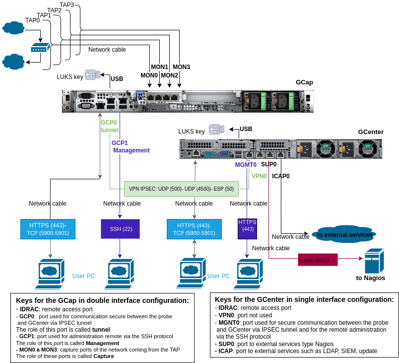
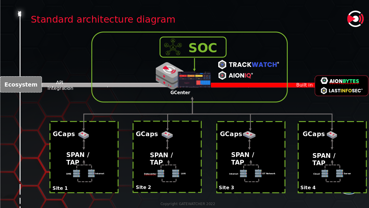
Below, diagrams are displayed representing the various inputs/outputs of the GCap and the GCenter and the corresponding communication flows.
For the GCap or for the GCenter, there are two possible configurations for communicating:
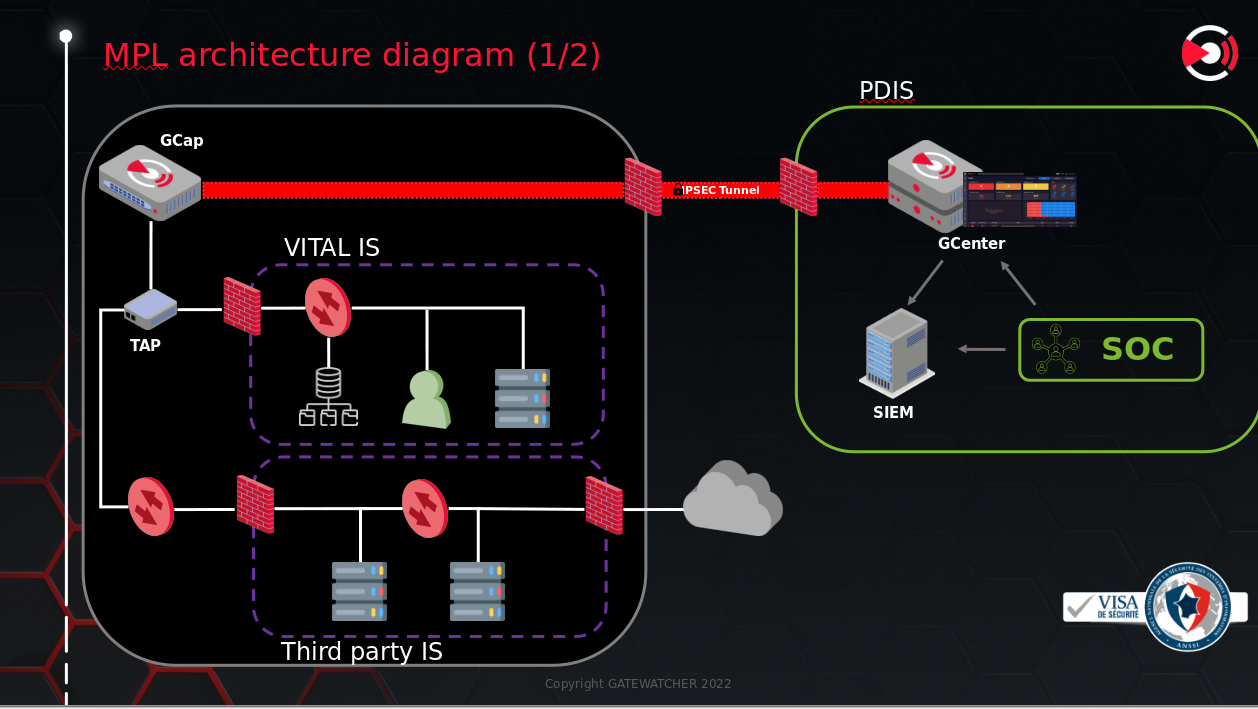
- The double interface configuration is the mandatory mode in the event of a sensitive environmentIn this configuration:
One network port is used for secure communication between the probe and the GCenter via IPSEC tunnel
Another network port is used for the remote administration via the SSH protocol
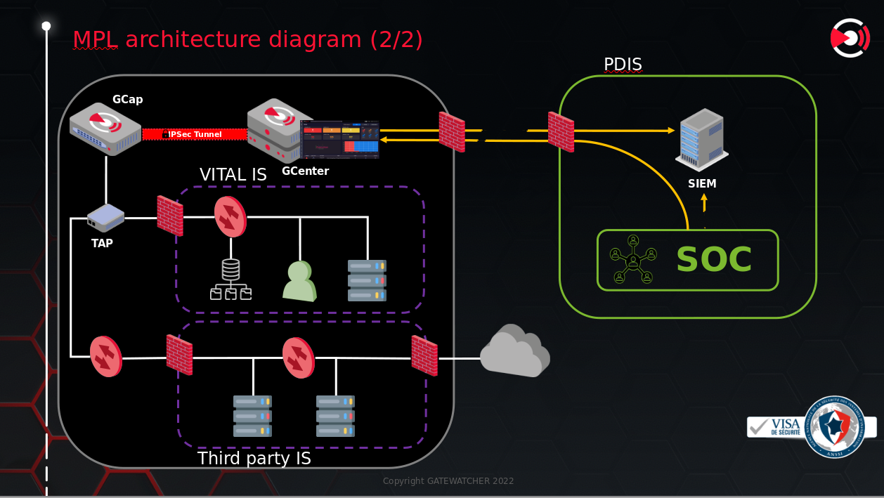
- The single interface configuration, only one network port is used:
For secure communication between the probe and the GCenter via IPSEC tunnel
For the remote administration via the SSH protocol
The four cases of configuration are shown below: